WELDING PROCESS 
CAN ALUMINUM BE WELDED WITH THE MIG/MAG PROCESS?
The answer is very simple: yes, it is possible. In fact, since the early development of the GMAW…
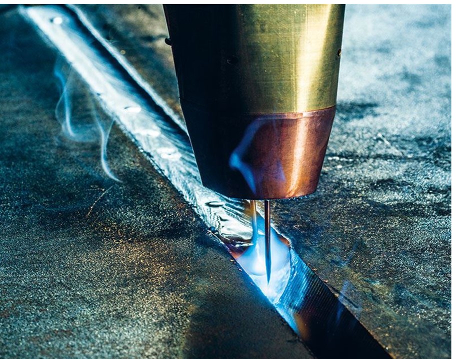
The MIG/MAG welding process (Gas Metal Arc Welding – GMAW) offers many advantages compared to other arc welding processes, such as improved productivity, consistent weld quality, and a wide range of industrial applications with respect to metal type and thickness.
The process can be operated in semiautomatic, mechanized, or robotic modes for automated processing. These systems and their benefits have led companies to implement them with the aim of increasing productivity and justifying the investment both from a cost standpoint and in terms of achieving adequate repeatability in weld quality. Technological advances in electronics have significantly helped transform the MIG/MAG process into one of the most widely used processes in the 21st century. They have also helped introduce synergic welding, which provides a control process that assists in establishing welding parameters. These advances have led to increased use and popularity of the process. However, regardless of how complex the process or equipment may be, many of the problems associated with this process are related to the wire feed unit, gun arrangement, and conduit liner assembly.
SOLUTIONS TO COMMON PROBLEMS IN THE MIG/MAG PROCESS.
Lack of knowledge results in considerable time and money being wasted on problems that can be easily resolved. For the GMAW welding process to perform at its best, it is important to carefully inspect the following elements.
Wire Feed Unit. This is arguably the most overlooked part of the equipment. It is uncommon for the drive roll pressure to be properly set for the type of wire being used. The wire guides that direct the wire from the spool to the torch are generally poorly selected, either too short to reach the wire drive rolls, or with an inner diameter too large for the wire diameter being used.
For carbon steel wires, smooth V-groove drive rolls are recommended; for aluminum welding, U-groove rolls are used. Taking sufficient time to properly set up the wire feed unit will save time and improve productivity by reducing feeding problems and achieving more consistent arc starts. Ensuring that the fundamentals are correctly adjusted on the wire feed unit will result in good weld quality, continuous wire feeding, and consistent welding current.
Torch Assembly. The connection from the wire feed unit to the welding torch assembly should be checked to prevent loss of fit; this is especially important when wire conduit liners have been replaced. Inadequate electrical connections and fittings tend to cause overheating problems, and in particular, increase electrical resistance, which causes the arc voltage to fluctuate and affects weld quality. The conduit liner, which is secured to the cable assembly, must be of adequate length and the correct size according to the wire diameter to be used. Typically, when it is installed and the excess is trimmed, it is left too short. It should be cleaned periodically to remove copper shavings and contaminants (grease, dust) to ensure continuous wire feeding. Excessive liner contamination is normally caused by excessive drive roll pressure on the wire. Drive roll pressure should be adjusted to achieve consistent wire feeding. Generally, pressure is set to the maximum, which creates feeding problems shortly after welding begins. The traditional method for cleaning the liner is to use compressed (dry) air to blow out accumulated debris.
Contact Tip. The contact tip is responsible for transferring the welding current. On occasion, an incorrect size is used (much larger than the wire diameter to be used). The contact tip must be sized specifically for the wire being used. It should be replaced periodically due to wear caused by the wire feeding through it. Many end users find high contact tip costs due to the large quantity used, and especially due to waste during welding operations. The wire tends to wear the contact tip on the lower portion due to continuous wire friction.
Nozzle. During the welding operation, the nozzle must be kept free of any spatter. A small amount of anti-spatter compound can affect the weld bead by generating porosity due to inadequate shielding gas coverage. The condition and position of the gas diffuser should also be verified. The design of the gas nozzle is important since the amperage and voltage to be used depend on it.
Ask the DoctorWelding assistant about this topic and it answers citing our articles.

The answer is very simple: yes, it is possible. In fact, since the early development of the GMAW…
Stainless steels are a group of materials whose main characteristic is corrosion protection, due to their CHROMIUM content,…