WELDING PROCESS 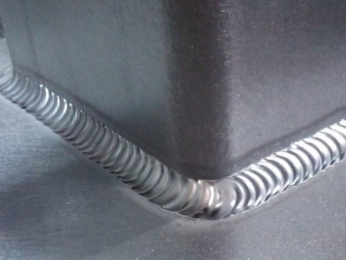
WELDING PROCESS
CAN ALUMINUM BE WELDED WITH THE MIG/MAG PROCESS?
The answer is very simple: yes, it is possible. In fact, since the early development of the GMAW…

HOW ELECTRODE ORIENTATION SHOULD BE
As in all arc welding processes, the orientation of the electrode with respect to the joint to be welded affects the shape of the weld bead and penetration. This effect on the weld bead is greater than that of arc voltage or travel speed. Electrode orientation is described in two ways: first, by the relationship between the electrode axis and the direction of travel (travel angle), and second, by the angle between the electrode axis and the surface of the workpiece (work angle). Electrode orientation has an effect on the width and penetration of the weld. When the electrode points in the direction opposite to the direction of travel, the technique is called backhand welding with a drag angle. When the electrode points in the direction of travel, the technique is known as forehand welding with a push angle. When the electrode is tilted away from perpendicular, giving it a lead angle with all other conditions unchanged, penetration decreases and the weld bead becomes wider and flatter. Maximum penetration in the flat position is achieved with the drag technique, using a drag angle of approximately 25° from perpendicular. This technique also produces a more convex and narrower weld bead, a more stable arc, and less spatter on the workpiece. For all positions, the travel angle generally used is a drag angle between 5° and 15° in order to maintain good control and shielding of the weld pool. For some materials, such as aluminum, a forehand technique is preferred; this technique produces a “cleaning action” ahead of the molten weld metal that reduces its surface tension and oxidation of the base metal. When fillet welds are required in the horizontal position (2F), the electrode should be positioned at approximately 45° to the vertical member (work angle).
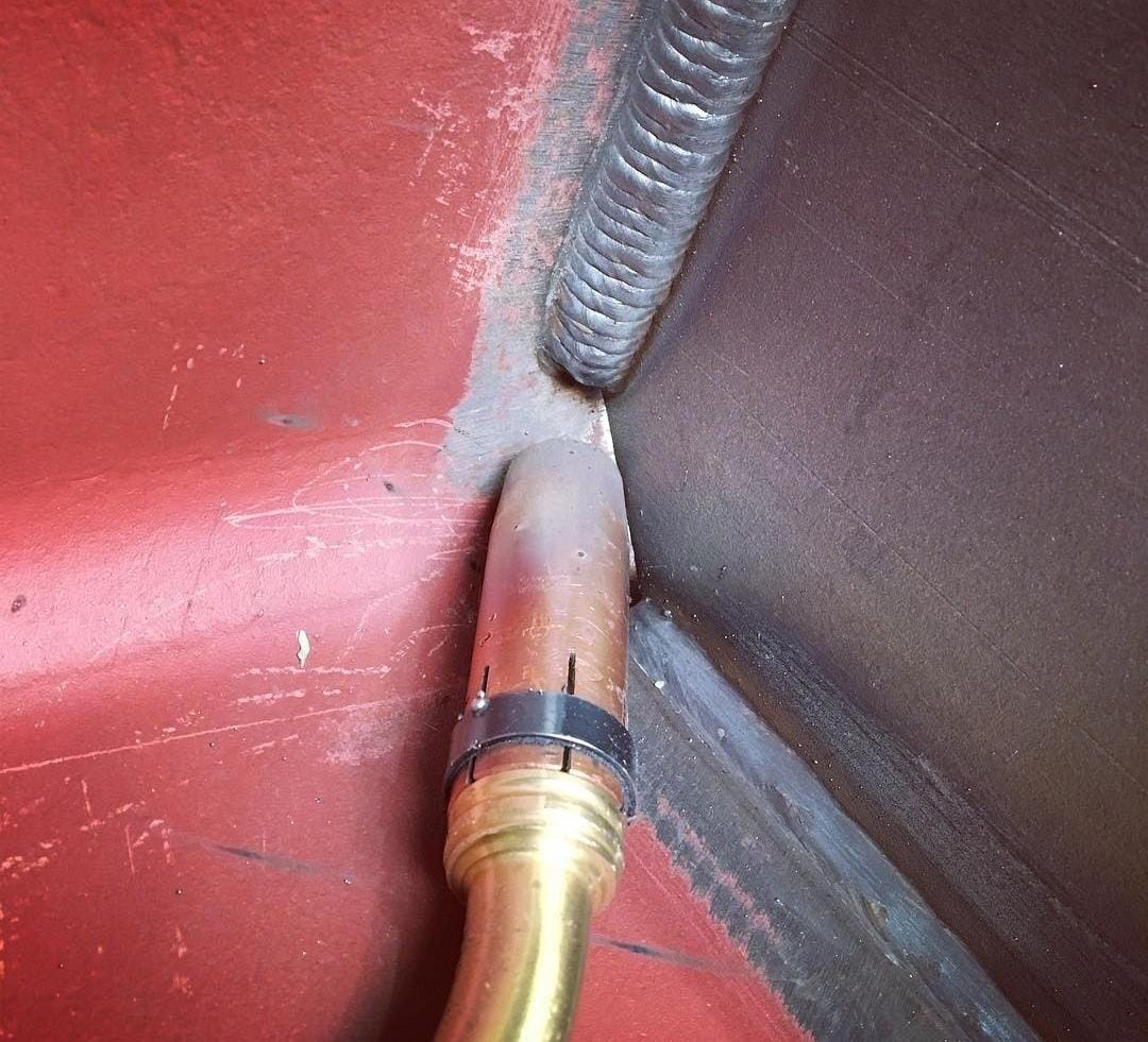
ELECTRODE EXTENSION. Electrode extension is the distance between the end of the contact tip and the tip of the electrode; increasing the electrode extension produces an increase in its electrical resistance. Resistance heating, in turn, causes the electrode temperature to rise, resulting in a slight increase in the electrode melt-off rate. In general, the higher electrical resistance produces a greater voltage drop between the electrode tip and the workpiece. This condition is immediately sensed by the power source, which compensates for this increase with a reduction in current; this immediately reduces the electrode melt-off rate and allows the physical arc length to shorten. Consequently, unless there is a voltage increase at the welding machine, the filler metal will be deposited in a narrow, high-crown bead. The desirable electrode extension is generally between ¼” to ½” (6 to 12 mm) for short-circuit transfer and ½” to 1″ (12 to 25 mm) for spray transfer.
Ask the DoctorWelding assistant about this topic and it answers citing our articles.
The answer is very simple: yes, it is possible. In fact, since the early development of the GMAW…
Stainless steels are a group of materials whose main characteristic is corrosion protection, due to their CHROMIUM content,…